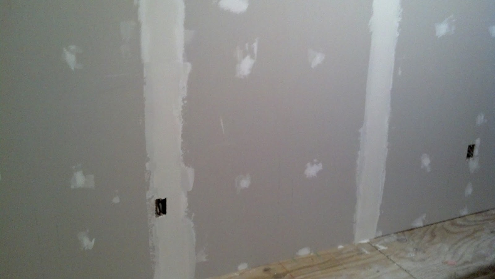
So I have made some pretty good progress over the past couple of weeks as you are about to see. I still have so much more to accomplish but it is all coming together and I couldn't be more pleased with the outcome thus far.
Now for the picture's.......

So I started the frame for the exhaust system by centering the bolts in alignment with the 2" X 4" stud's within the wall and ratcheting into the studs.......

After making sure they would tighten all the way I then removed them and put the 7/8" uni-strut, that was cut to fit, up onto the wall to bolt down.......

I made sure that it was plumb and level as I did with each piece I bolted together.......


Once the main frame was installed I attached the cross beams that the exhaust fans would attach to. I had ordered some 45 degree uni-strut brackets on E-Bay but they had not arrived at the time I built this but it is sturdy enough to hold the exhaust fans without them. I will install them as soon as they arrive.

As you can see that I marked and placed 3/8" spring nuts which will match up with the mounting holes on the exhaust fans.......

Now for the exhaust fans. They are stainless steel. The white you see is the protective film that was left on by the manufacture. I have decided to use the top knock-out for venting purposes as the vent holes and louvers are already installed and awaiting attachment to the exhaust fans.......


Once the main frame was installed I attached the cross beams that the exhaust fans would attach to. I had ordered some 45 degree uni-strut brackets on E-Bay but they had not arrived at the time I built this but it is sturdy enough to hold the exhaust fans without them. I will install them as soon as they arrive.

As you can see that I marked and placed 3/8" spring nuts which will match up with the mounting holes on the exhaust fans.......

Now for the exhaust fans. They are stainless steel. The white you see is the protective film that was left on by the manufacture. I have decided to use the top knock-out for venting purposes as the vent holes and louvers are already installed and awaiting attachment to the exhaust fans.......

I did not buy a kit but rather bought pieces of duct work to accomplish my goal.......


Once the pieces of duct were screwed together I used Great Stuff foam insulation to seal up the seams.......


I then installed the exhaust fans to the uni-strut frame that I had built.......


I then attached the vent ducts with the louver vents using steel flex hose and heat resistant ty-wraps.......


I then connected the power wires to the exhaust fans.......

And they worked perfectly.......

I almost was afraid they did not work as I had them on high. I soon found out that they were just that quite. They seem to be strong enough but if I find that they are not I will install what is called a in-line vortex fan which will be more than enough while using the same hoods. At this point I do not see me needing to do that though but it is an option.......

So now to install the ceiling grid and cut to fit the ceiling tile to fit around the vent ducts.......

And also the other side of the building as well.......

I then installed and bolted two pieces of strut to blocking that I had placed in the wall prior to sheet-rock to hold the weight of the main control panel.......


Like this.......

So one can install stuff like this.......

That panel does look awfully good in it's new home. It will look even better when it is in full operation helping make some really good beer. Or at least that is my dream.......


WOW! What a mess. Time to clean all that stuff up and get ready for the flooring.......

I have to make sure that I get every little piece of trash and metal off the floor before the sub-floor goes down.......

First piece of luan plywood underlayment goes down.......

Lots of sawdust to vacuum and sweep up as well.......

I used screws and screwed the luan down. Nails tend to pop up over time........

Then I laid the linoleum down.......

I carefully folded it back on itself until I could get the table moved carefully over to the other side of the building placed gently down onto the new flooring.......

Then using a pneumatic finish nailer I installed stained quarter-round molding around the base of the walls.......


I then used a wood filler pencil to fill all the holes made by the pneumatic nailer and also put a thin bead of silicon on top of the molding to seal it from any splashes making it's way down the wall and in behind the molding.......


I then drilled and taped 1/4"x 20 screws to attach the grounding conductors to.......

I then drilled a hole at the base of the wall and ran a #4 solid copper wire outside to attach to yet another ground rod. I sealed the hole with Great Stuff and silicone. I also attached ground clamps that will attach to the kettles at the flat side mounts of the kettles handles.......

Hooray!!!!!
The 45 degree uni-strut brackets finally made it.......
The 45 degree uni-strut brackets finally made it.......

That really sturdified (is that even a word?) the whole frame. Might be able to do chin-ups on it. Hehehehe Just kidding.......

Now time to get the conduit ran between the spa panel and the main control panel. I am running 1" EMT conduit. EMT is short for Electrical Metallic Tubing. It will have more than enough inner dimension to handle the 3 - #6's and a #10 ground as well as 3 - #12's for emergency control circuits. I started with cutting a hole in the lower left hand side of the panel and mounting a 1" myer's hub and a 1" seal-tight 90 degree flex connector.......

I then attached some 1" seal-tight flex and another connector and a "C" conduit body for wire pulling purposes. It would also serve as a place to pull the wire back to from the control panel if I for any reason needed to remove the panel to services it or change it out to another system altogether like a fully automated operators touchscreen interface with server and full internet access so I could operate any and all devices remotely from anywhere in the world. Hey! It sounds cool. I actually was already shown by one of my work acquaintances just how to do it. He had my logo up on his tablet PC and when he clicked on it this interface came up which showed my entire schematic and he was able to turn things off and on and manipulate the PID's for temperature as well. What a fun toy that would be. One of those items to place on the bucket list for when I win the lotto.......

I then installed the 1" EMT connector on the other end of the "C" conduit body and installed 1" EMT conduit from the main control panel over and down into the top of the spa panel.......


Then pulled the wire.......

I then pulled the backing off of the cork squares and stuck them to the top of the brew stand. I sealed the seams with silicon. These should help protect the top of the brew stand from the heat.......

Then it was finally time to start moving the other items, which had been stored in the other building, into there new home.......

Two fermentation chambers and the lone one just out of view to the far right is the chiller chamber for the cold water used with the 40 plate heat exchanger........

Here we see that one holds two corny kegs and a 5gal carboy.......

and another one holds two 6gal carboys.......

I may also get a upright refrigerator that will hold a 15gal conical fermenter but that will have to wait for now.


Now for another important part of the build. The fermentation chamber's control panel. What we have is a small panel with two Dwyer/Love TSS2 controller's and two duplex receptacles with the tab's broken off so each will be separately controlled for either the freezers compressor for dropping the temp, to a heat pad to raise the temp. The yeast are absolutely going to love these love controllers. (no pun intended).......


Well this is it for now. I still have plenty to do as I have to wire both the fermentation control panel as well as the main control panel and then put everything together. I still have to build a pump stand and install a 30gal. water bladder in the chill water chamber. But one thing is for sure, I'm a whole lot closer to brewing now than I was 6 months ago. Hehehehe.......
Happy brewing all!
More to come.......